Gun Drilling vs. BTA Drilling Selection: Matching Hole Diameter and Depth Ratios
1. Introduction: The Hole That Determines Which Process You Need
I have been specifying deep hole drilling processes for hydraulic, aerospace, and mold-making applications for over a decade, and I can tell you that the most expensive mistake in deep hole procurement is choosing the process before defining the hole.
Here is what that looks like in practice. A hydraulic cylinder manufacturer needs a 40mm diameter bore, 800mm deep, in a 4140 steel barrel. The L/D ratio is 20:1 — a deep hole by industry definition but not extreme. The manufacturer requests a quote from a shop that runs gun drilling. The shop quotes the job, but the cycle time is long because the gun drilling process is optimized for smaller diameters. The shop down the street that runs BTA drilling quotes a shorter cycle time and a lower per-part price — because BTA is the right process for a 40mm bore at 20:1 L/D. The difference in the quote is not quality. It is process selection.
The global deep hole drilling market continues to expand, driven by demand for hydraulic components, aerospace actuators, and precision mold cooling channels. But the selection between gun drilling and BTA drilling — the two dominant industrial methods — is not always well understood by the buyers placing the orders. Both processes produce deep, straight, accurate holes. They differ in how they evacuate chips, how fast they remove material, and what range of diameters and depth ratios they handle efficiently.
This guide breaks down the selection decision — the diameter range, the depth-to-diameter ratio, the chip evacuation mechanism, the accuracy and surface finish, the machine and tooling requirements, and the decision framework that matches the process to the hole.
2. How the Two Processes Actually Differ
The two processes share the same fundamental challenge — drilling a hole that is many times deeper than its diameter without the drill wandering, without the chips jamming, and without the heat building up to the point where the tool fails. They solve that challenge in opposite ways.
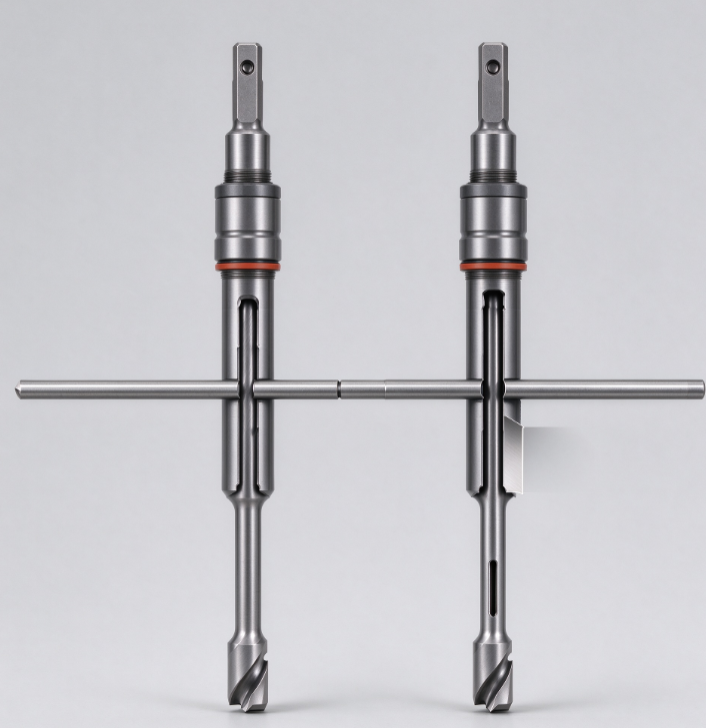
Gun drilling uses a single-edge cutting tool with a straight fluted shaft. The cutting fluid is pumped through the interior of the tool and exits at the cutting tip. The chips are flushed back out of the hole along an external V-groove on the outside of the drill shaft. The process is called “external chip evacuation” — the chips exit the hole on the outside of the tool, in the space between the tool shaft and the hole wall.
The single-edge design makes the tool self-guiding. The cutting force is balanced against a guide pad that presses against the opposite side of the hole, keeping the drill centered and straight. This is why gun drilling holds straightness so well — the tool steers itself along the hole axis rather than deflecting away from it.
BTA drilling — named after the Boring and Trepanning Association — uses a multi-edge cutting head mounted on a tubular drill shank. The cutting fluid enters the cutting zone through the annular gap between the drill tube and the hole wall. The chips are carried away through the hollow interior of the drill tube — “internal chip evacuation.” The process is also called STS (Single Tube System) or ejector drilling depending on the specific configuration.
The multi-edge design and the internal chip evacuation allow BTA drilling to remove material much faster than gun drilling. The larger chip passages and the higher coolant volume mean the process can run at higher feeds and speeds without chip jamming. The trade-off is that the tool requires a dedicated deep hole drilling machine with a high-pressure coolant system and a pressure head to force the coolant through the annular gap.
Process Parameter | Gun Drilling | BTA Drilling |
Cutting edges | Single edge | Multi-edge |
Chip evacuation | External — along V-groove | Internal — through drill tube |
Coolant path | Through tool interior, exits at tip | Through annular gap, exits through tube |
Tool design | Self-guiding — force balanced by guide pad | Guided by support bearings |
Machine requirement | Lathe or dedicated gun drilling machine | Dedicated BTA machine with pressure head |
Chip evacuation efficiency | Lower — chips travel along outside of tool | Higher — chips travel through large internal passage |
3. Diameter Range: Where Each Process Makes Sense
The diameter of the hole is the first selection variable. Each process has an optimal diameter range, and the overlap zone is where the decision becomes a matter of economics rather than capability.
Gun drilling is optimised for smaller diameters, typically between 1mm and 38mm. The common production range is 3mm to 50mm, with special equipment extending to 75mm. The process becomes less efficient above 50mm because the single-edge tool removes material at a slower rate than a multi-edge tool, and the external chip evacuation becomes less effective as the hole diameter increases.
BTA drilling is designed for larger diameters, typically 20mm and above. The production range extends from 20mm to 300mm for solid boring, with counter-boring capabilities up to 500mm. The process is most efficient at diameters above 40mm, where the multi-edge cutting head and the internal chip evacuation can deliver their full productivity advantage.
The overlap zone is 20mm to 50mm. In this range, both processes can produce the hole. The selection depends on the depth-to-diameter ratio, the production volume, and the machine availability. For a 30mm diameter hole at 20:1 L/D, gun drilling is a viable option. For a 30mm hole at 15:1 L/D and a production volume of 500 parts per month, BTA drilling may deliver a lower per-part cost because of its higher material removal rate.
Diameter Range | Recommended Process | Notes |
1–3 mm | Gun drilling only | Micro-drilling with special equipment |
3–20 mm | Gun drilling | BTA tooling not practical below 20mm |
20–40 mm | Either — depends on L/D and volume | Overlap zone |
40–75 mm | BTA preferred | Gun drilling possible but less efficient |
75–300 mm | BTA only | Gun drilling not practical |
300–500 mm | BTA counter-boring | Specialized large-diameter equipment |
4. Depth-to-Diameter Ratio: The Selection Variable That Overrides Everything
The depth-to-diameter ratio — L/D — is the single most important variable in deep hole drilling. It determines the difficulty of the hole, the risk of tool deflection, the chip evacuation challenge, and the process capability.
A 100mm deep hole at 20mm diameter has an L/D of 5:1. The same 100mm depth at 5mm diameter has an L/D of 20:1. The diameter — not the depth — is the critical variable, because it determines tool stiffness, chip volume per revolution, and coolant delivery channel size simultaneously.
Gun drilling can achieve L/D ratios of 100:1 or more, and advanced systems reach 300:1 to 400:1 for micro-drilling applications. The self-guiding single-edge design is what makes these extreme ratios possible. The tool steers itself along the hole axis, and the external chip evacuation keeps the cutting zone clear even at extreme depths.
BTA drilling also achieves L/D ratios of 100:1 or more, with published capability up to 200 times the diameter for solid boring. However, the practical limit for BTA drilling is typically lower than gun drilling because the internal chip evacuation requires a larger coolant volume and higher pressure. At extreme L/D ratios, the pressure drop through the drill tube becomes the limiting factor.
L/D Ratio | Classification | Gun Drilling | BTA Drilling |
≤ 5:1 | Standard hole | Over-specified | Over-specified |
5:1–10:1 | Semi-deep | Capable | Capable |
10:1–20:1 | Deep hole | Excellent | Excellent |
20:1–50:1 | Very deep | Excellent | Excellent — preferred for larger diameters |
50:1–100:1 | Ultra-deep | Excellent | Capable — pressure-dependent |
100:1+ | Extreme | Capable — up to 300:1+ | Limited by coolant pressure |
5. Chip Evacuation: The Hidden Variable That Drives the Selection
Chip evacuation is the fundamental engineering challenge in deep hole drilling. In a conventional twist drill, the chips must travel up the helical flutes to exit the hole. At an L/D ratio of 10:1, this is manageable. At 20:1 or 30:1, the chips pack into the flutes, causing recutting, surface degradation, and eventually complete chip jamming that breaks the drill.
Both gun drilling and BTA drilling solve this problem — but in different ways, with different consequences for the achievable material removal rate.
Gun drilling chip evacuation. The cutting fluid is pumped through the interior of the drill and exits at the cutting tip. The chips are carried back along the external V-groove of the drill shaft. The chip passage is the space between the drill shaft and the hole wall — a narrow, continuous channel that runs the full length of the hole. The coolant pressure required to keep the chips moving increases with depth. For a 10mm diameter hole at 100:1 L/D, the coolant pressure may need to be 50 to 150 bar to maintain chip flow.
The external chip evacuation is effective for small diameters because the chip volume per revolution is small. The single-edge tool produces a thin chip that is easy to flush. But as the diameter increases, the chip volume increases proportionally, and the external channel becomes the limiting factor. This is why gun drilling loses its efficiency advantage above 50mm.
BTA drilling chip evacuation. The cutting fluid enters through the annular gap between the drill tube and the hole wall, flows to the cutting head, and carries the chips back through the interior of the drill tube. The chip passage is the full internal diameter of the tube — a large, unobstructed channel that can handle the higher chip volume produced by the multi-edge cutting head.
The internal chip evacuation is why BTA drilling can remove material three times faster than gun drilling at equivalent diameters. The larger chip passage allows higher feed rates and higher cutting speeds without the risk of chip jamming. The trade-off is that the process requires a dedicated machine with a pressure head to force the coolant through the annular gap at the required pressure and volume.
Chip Evacuation Parameter | Gun Drilling | BTA Drilling |
Chip path | External — V-groove | Internal — drill tube |
Chip passage size | Narrow — between tool and hole wall | Large — full tube interior |
Coolant pressure required | 50–150 bar | 20–80 bar (but higher volume) |
Chip volume capacity | Limited by external channel | High — large internal passage |
Material removal rate | Baseline | 3× higher at equivalent diameter |
Depth limitation | Chip flow resistance increases with depth | Pressure drop through tube limits extreme L/D |
6. Head-to-Head: Complete Process Comparison Table
Parameter | Gun Drilling | BTA Drilling |
Cutting edge configuration | Single edge | Multi-edge |
Optimal diameter range | Ø1–38 mm | Ø20–300 mm |
Extended diameter range | Up to 75 mm | Up to 500 mm (counter-boring) |
L/D capability | Up to 100:1+; 300:1+ with advanced systems | Up to 100:1+; practical limit lower due to pressure drop |
Chip evacuation | External — V-groove | Internal — drill tube |
Material removal rate | Baseline | 3× higher at equivalent diameter |
Coolant pressure | 50–150 bar | 20–80 bar (higher volume) |
Straightness | 0.05–0.1 mm over 300–600 mm | 0.08 mm over 100 mm typical |
Surface finish (as-drilled) | Ra ≤ 1.6 µm | Ra ≤ 1.2 µm |
Machine requirement | Lathe or dedicated gun drilling machine | Dedicated BTA machine with pressure head |
Tooling cost | Lower | Higher |
Setup complexity | Moderate | Higher — dedicated machine and pressure head |
Best application | Small to medium diameters, high L/D, high straightness | Medium to large diameters, high volume, high removal rate |
Typical industries | Medical, firearms, mold cooling, small hydraulic | Hydraulic cylinders, oil and gas, aerospace actuators, large mold bores |
7. Accuracy and Surface Finish: What You Get As-Drilled
Both processes produce holes that are accurate enough to eliminate secondary operations in many applications. The differences are in the achievable tolerance, the straightness over depth, and the surface finish.
Gun drilling accuracy. Gun drilling achieves straightness within 0.05–0.1 mm over 300–600 mm depth and surface finish of Ra ≤ 1.6 µm as-drilled. The hole diameter tolerance is typically IT8 to IT9 — approximately ±0.02 to ±0.05 mm depending on the diameter. In many applications, the gun-drilled hole requires no reaming or honing because the surface finish and dimensional accuracy are already within specification.
BTA drilling accuracy. BTA drilling achieves hole wall roughness between 0.3 and 0.6 µm in low-carbon alloy steel, with a maximum microhardness of approximately 2.15 times the matrix hardness and compressive residual stress in the surface layer. The compressive residual stress is a quality advantage — it improves fatigue resistance compared to a tensile stress condition. The diameter tolerance is typically H8 to H9 (approximately ±0.02 to ±0.05 mm depending on the diameter), and the straightness is within 0.08 mm per 100 mm.
The practical selection question is not “which process is more accurate” — both are accurate enough for most deep hole applications. It is “which process delivers the required accuracy at the lowest total cost.” For a 20mm hole at 30:1 L/D, both processes will deliver a straight, round hole with a finish that meets most hydraulic cylinder specifications. The decision comes down to diameter, volume, and machine availability.
Quality Parameter | Gun Drilling | BTA Drilling |
Diameter tolerance | IT8–IT9 | H8–H9 |
Straightness | 0.05–0.1 mm / 300–600 mm | 0.08 mm / 100 mm |
Surface roughness (as-drilled) | Ra ≤ 1.6 µm | Ra ≤ 1.2 µm |
Residual stress | Typically tensile or neutral | Compressive — improves fatigue life |
Reaming/honing required | Often not required | Often not required |
Roundness | Good | Good — influenced by cutting speed, feed, chip flow |
8. Machine and Tooling Requirements
The machine and tooling requirements determine the capital investment and the operational complexity of each process. This is where the selection becomes a business decision, not just a technical one.
Gun drilling machine requirements. Gun drilling can be performed on a lathe or on a dedicated gun drilling machine. A lathe-based setup is lower cost but limited in the achievable L/D ratio and the production rate. A dedicated gun drilling machine with counter-rotation capability — rotating both the tool and the workpiece — achieves the best results on large L/D holes. The machine requires a high-pressure coolant system capable of delivering 50–150 bar, a rigid tool holder, and a chip collection system for the external chip evacuation.
BTA drilling machine requirements. BTA drilling requires a dedicated deep hole drilling machine with a pressure head that forces the coolant through the annular gap between the drill tube and the hole wall. The machine must have a high-volume, high-pressure coolant system, a rigid spindle, and a support system for the long drill tube. The pressure head is the critical component — it must seal against the workpiece while allowing the drill tube to rotate and advance. This is why BTA machines are more expensive than gun drilling machines and why the process is typically used for higher-volume production.
Tooling cost comparison. Gun drilling tooling is less expensive than BTA tooling because the tool is simpler — a single-edge carbide tip on a fluted shaft. BTA tooling is more expensive because the cutting head has multiple edges, the drill tube must be precision-matched to the pressure head, and the support bearings add complexity. However, the BTA tooling cost is offset by the higher material removal rate and the longer tool life in high-volume production.
Machine and Tooling Parameter | Gun Drilling | BTA Drilling |
Machine type | Lathe or dedicated gun drilling machine | Dedicated BTA machine with pressure head |
Counter-rotation capability | Available on dedicated machines | Standard on BTA machines |
Coolant pressure | 50–150 bar | 20–80 bar (higher volume) |
Tooling cost | Lower | Higher |
Tool life | Moderate — single-edge wear | Higher — multi-edge distributes load |
Setup time | Moderate | Higher — pressure head and tube alignment |
Capital investment | Lower | Higher |
9. The Selection Decision Matrix
The selection decision follows a logical sequence. Start with the diameter, then the L/D ratio, then the production volume, and finally the machine availability.
Hole Diameter | L/D Ratio | Production Volume | Recommended Process | Rationale |
1–20 mm | Any | Any | Gun drilling | BTA tooling not practical below 20mm |
20–40 mm | > 50:1 | Low–Medium | Gun drilling | BTA chip evacuation less effective at extreme L/D |
20–40 mm | 10:1–50:1 | Medium–High | Either — evaluate | Overlap zone; decision based on volume and machine availability |
20–40 mm | 10:1–50:1 | High | BTA | Higher removal rate reduces cycle time |
40–75 mm | Any | Low–Medium | BTA | Gun drilling inefficient at this diameter |
40–75 mm | Any | High | BTA | Maximum productivity advantage |
75–300 mm | Any | Any | BTA | Gun drilling not practical |
300–500 mm | Any | Any | BTA counter-boring | Specialized large-diameter equipment |
How to read this matrix. The diameter is the first gate. Below 20mm, gun drilling is the only option. Above 75mm, BTA is the only option. The L/D ratio is the second gate. At extreme L/D ratios (above 50:1), gun drilling retains its advantage because the external chip evacuation is less sensitive to pressure drop than the internal evacuation of BTA. The production volume is the third gate. At high volumes, BTA’s higher material removal rate delivers a lower per-part cost even in the overlap zone.
10. Case Study: A Hydraulic Cylinder Manufacturer’s Bore Selection
The most instructive case study for the gun drilling versus BTA selection comes from a hydraulic cylinder manufacturer producing 500 cylinders per month.
The component. A hydraulic cylinder barrel, 40mm bore diameter, 800mm deep, in 4140 steel. The L/D ratio is 20:1. The bore tolerance is H8 (approximately +0.039/0 mm). The surface finish requirement is Ra ≤ 1.6 µm. The production volume is 500 barrels per month — 6,000 per year.
The original process. The manufacturer used gun drilling on a lathe-based setup. The cycle time was 18 minutes per barrel. The tool life was approximately 15 barrels per tool. The surface finish was within specification, and the straightness was acceptable. The process worked, but it was slow.
The evaluation. The manufacturer evaluated BTA drilling for the same part. A local shop with a BTA machine quoted a cycle time of 6 minutes per barrel — a 3× reduction. The tool life was approximately 40 barrels per tool — a 2.7× improvement. The surface finish was Ra ≤ 1.2 µm, better than the gun drilling specification. The diameter tolerance was H8, within specification.
The decision. The manufacturer switched to BTA drilling for the 40mm bore. The cycle time reduction from 18 minutes to 6 minutes recovered 12 minutes per barrel. At 500 barrels per month, that is 6,000 minutes — 100 hours — of recovered machine time per month. The tooling cost per barrel decreased because of the longer tool life. The surface finish improvement eliminated a light honing operation that had been required after gun drilling.
The lesson. The 40mm diameter and 20:1 L/D ratio placed the part squarely in the overlap zone. Both processes were technically capable. The decision was economic — BTA drilling delivered a 3× cycle time reduction and a 2.7× tool life improvement. The manufacturer did not need a new machine; they outsourced the BTA drilling to a local shop and retained the gun drilling capability for smaller diameter work. The selection was not “which process is better” but “which process is better for this specific hole at this specific volume.”
11. Practical Sourcing Framework for B2B Buyers
If you are sourcing deep hole drilling services, here is the framework I recommend.
Step 1: Define the hole first. Diameter, depth, L/D ratio, tolerance, surface finish, material, and production volume. These six parameters determine the process selection before any supplier conversation begins.
Step 2: Match the diameter to the process range. Below 20mm — gun drilling. Above 75mm — BTA. In the 20–75mm range — evaluate both processes based on the L/D ratio and the volume.
Step 3: Calculate the L/D ratio and compare to the process capability. Gun drilling excels at L/D ratios above 50:1. BTA drilling excels at L/D ratios between 10:1 and 50:1 for larger diameters. At extreme L/D ratios (100:1+), gun drilling is the more reliable process.
Step 4: Evaluate the production volume economics. For high-volume production in the overlap zone (20–75mm diameter, 10:1–50:1 L/D), BTA drilling typically delivers a lower per-part cost because of the higher material removal rate and the longer tool life. For low-volume or one-off parts, gun drilling may be more economical because the setup is simpler.
Step 5: Verify the machine and tooling availability. Gun drilling can be performed on a lathe or a dedicated machine. BTA drilling requires a dedicated machine with a pressure head. If the supplier does not have the right machine for the hole, the process selection is determined by the available equipment, not the optimal process.
Step 6: Request sample parts and verify the accuracy. Before committing to a production order, request sample holes and measure the diameter, straightness, roundness, and surface finish. The sample test reveals process capability that the supplier’s marketing material does not capture.
Sourcing Parameter | Gun Drilling | BTA Drilling |
Diameter range | Ø1–38 mm (up to 75 mm) | Ø20–300 mm (up to 500 mm counter-boring) |
L/D capability | 100:1+ (300:1+ advanced) | 100:1+ (practical limit lower) |
Material removal rate | Baseline | 3× higher |
Surface finish (as-drilled) | Ra ≤ 1.6 µm | Ra ≤ 1.2 µm |
Diameter tolerance | IT8–IT9 | H8–H9 |
Straightness | 0.05–0.1 mm / 300–600 mm | 0.08 mm / 100 mm |
Machine requirement | Lathe or dedicated gun drilling machine | Dedicated BTA machine with pressure head |
Best volume | Low to medium | Medium to high |
12. Frequently Asked Questions
Q: What is the main difference between gun drilling and BTA drilling?
Gun drilling uses a single-edge cutting tool with external chip evacuation — the chips exit the hole along a V-groove on the outside of the tool shaft. BTA drilling uses a multi-edge cutting head with internal chip evacuation — the chips exit through the hollow interior of the drill tube. BTA drilling removes material three times faster than gun drilling at equivalent diameters, but requires a dedicated machine with a pressure head.
Q: At what diameter should I switch from gun drilling to BTA drilling?
The switch is typically at 20mm diameter. Below 20mm, gun drilling is the only practical option because BTA tooling is not available in smaller sizes. Above 40mm, BTA drilling is the more efficient option. In the 20–40mm range, both processes are capable, and the decision depends on the L/D ratio and the production volume.
Q: Can BTA drilling achieve the same L/D ratios as gun drilling?
BTA drilling can achieve L/D ratios of 100:1 or more, but the practical limit is lower than gun drilling because the internal chip evacuation requires a higher coolant volume and pressure. At extreme L/D ratios (above 50:1), the pressure drop through the drill tube becomes the limiting factor. Gun drilling’s external chip evacuation is less sensitive to depth.
Q: Which process gives better surface finish?
BTA drilling typically delivers a slightly better surface finish — Ra ≤ 1.2 µm compared to Ra ≤ 1.6 µm for gun drilling. BTA drilling also produces compressive residual stress in the surface layer, which improves fatigue resistance. In many applications, both processes eliminate the need for reaming or honing.
Q: How much faster is BTA drilling than gun drilling?
BTA drilling removes material approximately three times faster than gun drilling at equivalent diameters. The higher material removal rate is the result of the multi-edge cutting head and the internal chip evacuation, which allows higher feed rates and cutting speeds without chip jamming.
Q: Do I need a dedicated machine for BTA drilling?
Yes. BTA drilling requires a dedicated deep hole drilling machine with a pressure head that forces the coolant through the annular gap between the drill tube and the hole wall. Gun drilling can be performed on a lathe or a dedicated gun drilling machine — the machine requirement is less specialized.
Q: What is the typical straightness for each process?
Gun drilling achieves straightness within 0.05–0.1 mm over 300–600 mm of depth. BTA drilling achieves straightness within 0.08 mm per 100 mm of depth. Both processes produce holes that are straight enough for most hydraulic and aerospace applications.
Q: Can both processes be used in the same shop?
Yes. Some machine builders offer combined gun drilling and BTA drilling machines that can switch between the two processes. This allows a shop to handle the full range of diameters and L/D ratios with a single machine investment. The selection then becomes a matter of cycle time optimization rather than machine capability.
13. Final Thoughts
Let me leave you with this.
The choice between gun drilling and BTA drilling is not a choice between a good process and a bad one. It is a choice between two processes that solve the same problem — drilling a deep, straight, accurate hole — in different ways. Gun drilling uses a single-edge self-guiding tool and external chip evacuation to achieve extreme L/D ratios at small to medium diameters. BTA drilling uses a multi-edge cutting head and internal chip evacuation to achieve higher material removal rates at medium to large diameters.
The data is clear. Gun drilling is optimised for Ø1–38mm with L/D ratios up to 100:1 or more. BTA drilling is optimised for Ø20–300mm with material removal rates three times higher than gun drilling. The overlap zone is 20–40mm, where the decision depends on the L/D ratio and the production volume. Gun drilling achieves Ra ≤ 1.6 µm and straightness of 0.05–0.1mm over 300–600mm. BTA drilling achieves Ra ≤ 1.2 µm and straightness of 0.08mm per 100mm. And the hydraulic cylinder case study demonstrates that a 40mm bore at 20:1 L/D was better served by BTA drilling — a 3× cycle time reduction and a 2.7× tool life improvement.